Introduction
Liquid Crystal Displays are used in many devices like micro oven, calculators etc. They play a very important role in embedded systems. Many electronic displays are used in embedded system such as 7 segment, LED displays but they have their own limitations. In the previous articles we have seen interfacing LCD to different microcontrollers like AVR, 8051 and PIC. In this tutorial, let us see interfacing an LCD with Arduino.
Compared to other controllers, Interfacing LCD with Arduino is very easy. In in other microcontrollers, one should write the complete code for the working of LCD where as arduino provides a very good platform for non-programmers. Let us see the interfacing clearly.
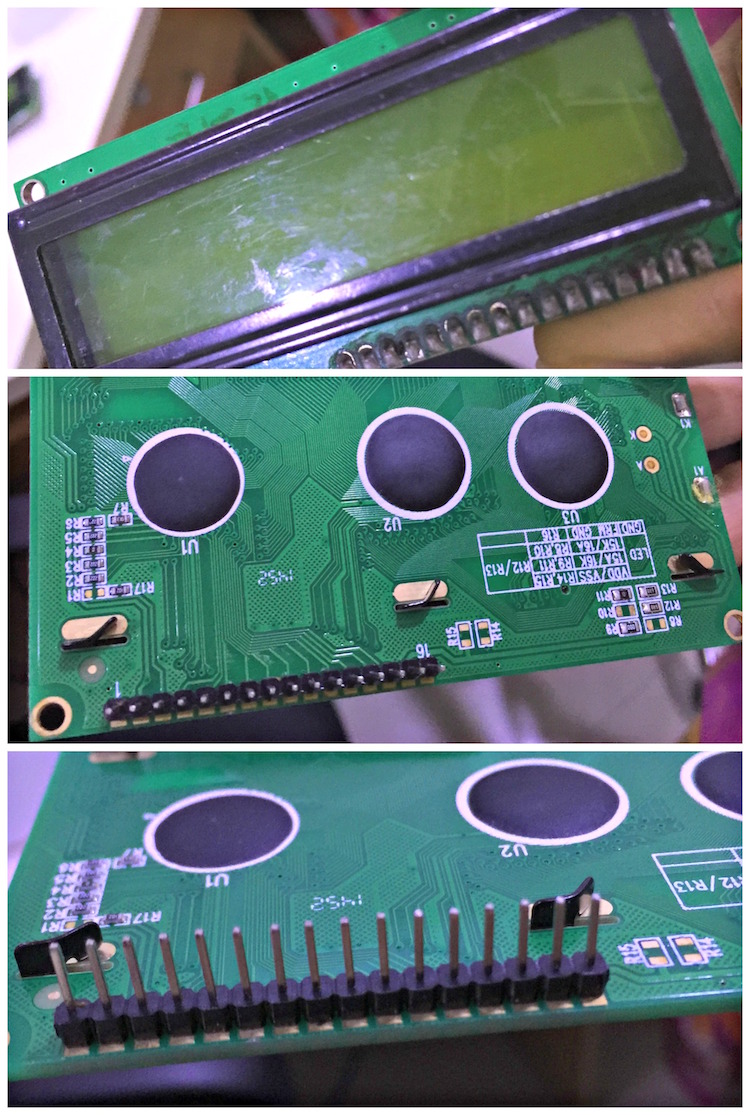
16X2 LCD is the most commonly used LCD Display.16X2 indicates that it can display 32 characters in 2 lines. It has 16 pins. They are shown below.
LCD Pin Configuration
| Pin 1 | GND |
| Pin 2 | +5V |
| Pin 3 | Mid terminal of potentiometer (for brightness control) |
| Pin 4 | Register Select (RS) |
| Pin 5 | Read/Write (RW) |
| Pin 6 | Enable (EN) |
| Pin 7 | DB0 |
| Pin 8 | DB1 |
| Pin 9 | DB2 |
| Pin10 | DB3 |
| Pin 11 | DB4 |
| Pin 12 | DB5 |
| Pin 13 | DB6 |
| Pin 14 | DB7 |
| Pin 15 | +4.2-5V |
| Pin 16 | GND |
Pin Description
Data Pins: Pin7 to Pin14 are data Pins.
Vss: It is the Ground Pin of the module.
Vdd : It is the supply pin of the module.
VEE : Pin3 is used for controlling the brightness of the LCD. Normal setting of this pin is between 0.4V to 0.9V.A 10 k pot is connected to adjust the brightness of the screen.
Register Select : RS pin is used to select the register. There are two registers in this LCD. They are data register data instruction register. Data register sends data to the screen while instruction register sends Commands to LCD’s controller, which controls the instructions.
Logic High (1) – Activates Data register.
Logic Low (0) – Activates Instruction register.
RW selects either read or write mode. In this this pin is connected to ground.
Logic High (1) – Activates Read mode.
Logic Low (0) – Activates Write mode.
Enable: E enables the LCD module.
LCD can be used either in 4-bit mode or 8-bit mode. In 4-bit mode it requires 7 IO pins of the Arduino. In 8 bit mode 11 IO pins required from arduino. In order to understand the interfacing let us see examples.
Project Example:
Components:
- 16X2 LCD
- Arduino
- Connecting wires.
Circuit Diagram:
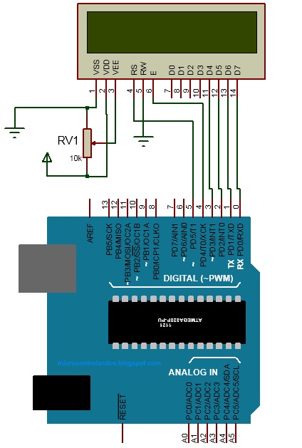
Circuit Connections
- The four data Pins D4 to D7 are connected to the four pins (0 to 3) of the arduino.
- Rs (register select) and E (Enable) pins are connected to the pin4 and pin5 of the arduino.
- VSS pin of the LCD is connected to the ground while VDD is connected to the power supply.
- V EE of LCD is connected to the potentiometer in order to vary the brightness of the LCD.
- RW pin is connected to ground.
Code (Sketch)
The above program shows the LCD displaying Electronicshub and 16X2 LCD strings.
Arduino provides an in built library for LCD. Header file is Liquid Crystal.h is declared in order to fetch all the functions from the library. This can support 8-bit mode or 4-bit mode of operation.
Next line “ Liquid Crystal lcd(RS,E,D4,D5,D6,D7) “defines the pins of arduino that are interfaced to LCD. For example in our circuit RS pin of LCD is connected to pin5 of the arduino. 5 is written in place of RS.
In setup ( ) function LCD initialization is done.AS the initialization of LCD is done only once it is declared in Setup( ) function. Void indicates no return values.
Next line of code is “lcd.begin(16×2)”.16 x 2 indicates the number of rows and columns of the LCD.
Void loop( ) indicates the continuous execution of the statement. The instruction in this loop are repeated until the controller resets.
Lcd.setCursor (columns, rows) sets the cursor point. Remember that there are only 2 rows and 16 columns in the LCD.
Lcd.print(“ ”) prints the string written to it.
Thus the above sketch simply displays the String on the LCD.In order to scroll the display, below code can be used.
void loop()
{
for( int i=0; i<2; i++)
{
lcd.scrollDisplayLeft(); //scrolls display left by two positions
}
delay(500); //sets the speed at which display moves
}
For this print the string in Void setup ( ) function.

2 Responses
how to interface web camera with arduino?
Regarding set up instructions I found code line
“LiquidCrystal lcd (5, 4, 3, 2, 1, 0)” to not work
change to
“LiquidCrystal lcd (4, 5, 0, 1, 2, 3)”
seems to resolve the problem
just a note for us newbies!!!