As mentioned in our Arduino based DC Motor control project, a DC Motor is one of the most commonly used electric motor in electronics, robotics, toys etc. It generally consists of only two wires for electrical connection. When these wires are properly connected and given electrical supply (like a battery), the motor starts rotating. A technique called Pulse Width Modulation (PWM) allows us to control the speed of rotation of the motor.
The story of Servo Motor is entirely different from that of a DC Motor. A Servo Motor is a type of actuator that provides high precision control of linear or angular position. A typical servo motors consists of four things (or parts): a DC Motor (or AC Motor), a gear unit, a position and speed sensing device and a control unit.
Servo Motors are used in applications where very high precision motion is required like assembly robots, computer numeric controls etc.
In this project, we are going to control the position of a Servo Motor using Arduino UNO board.
Circuit Diagram
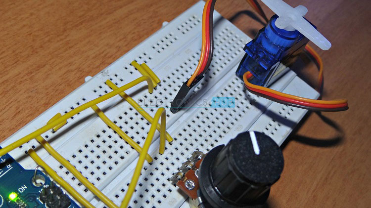
Components
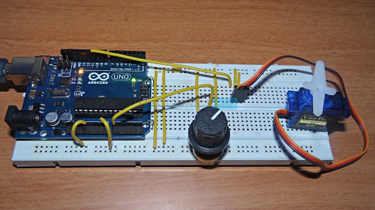
- Arduino UNO Board
- Tower Pro SG90 Servo Motor
- 10KΩ Potentiometer
- 5V Power Supply
- Breadboard
- Connecting wires
Component Description
Arduino UNO
The main processing module of the project is Arduino UNO board. Its features like Analog to Digital Converter (ADC) and Pulse Width Modulation (PWM) are used in this project.
Servo Motor
As mentioned in the introduction, a servo motor is a type of DC motor which is used for precision control. Servo motors are available as both AC Servo motors and DC Servomotor with each type having its own areas of applications.
A simple servo motor (as the one used in this project) consists of a small DC motor, a potentiometer for providing position feedback, a gear system for increased torque and a control system.
Typically, simple servo motors consists of three wires. These are usually color coded as Red, Brown and Orange (may vary with different models). The Red wire is used for supply, the Brown wire is used for ground and the Orange wire is used for control signal.
Here, the control signal will determine the position of the servo motor’s shaft. The control signal is usually a PWM signal but this PWM signal is not used to control the speed of the motor as in case of a DC Motor. But rather, it is used to determine the position of the servo meter.
The DC Motor in the servo motor is powered as per the control signal it receiver. As per the feedback from the position sensing system (like a potentiometer), when the servo achieves the desired position, the power to the motor is terminated.
Even though the power supply to the motor inside the servo motor is not constant, the overall power should be constant as the servo motor has a dedicated system that controls the power.
The servo motor used in this project is Tower Pro SG90. It is a small but powerful servo motor that can produce a torque of 1.8 kgf.cm.
Circuit Design
The main components of this project are Arduino UNO board and servo motor. The design of the circuit is pretty straight forward. As mentioned earlier, a servo motor has three wires: two for electrical connection and one for control signal.
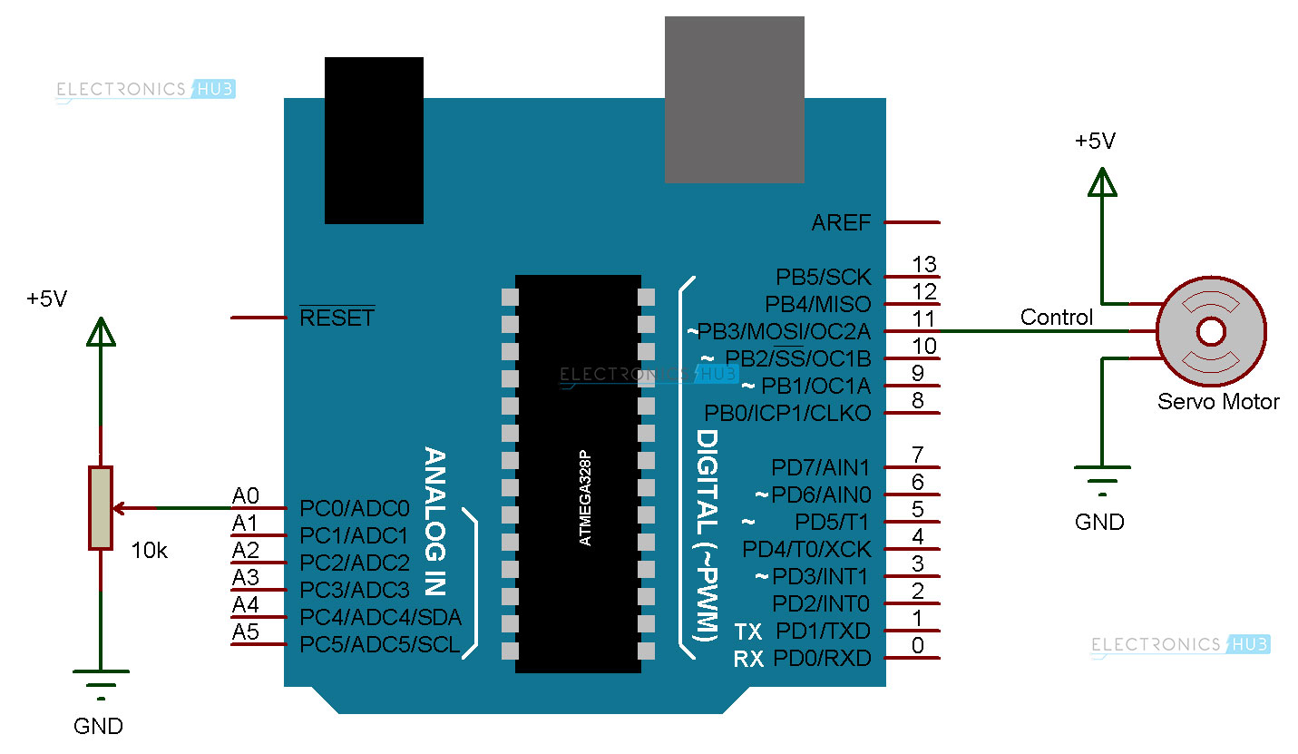
So, connect the red wire to +5V supply and brown wire to ground. As the control signal is a PWM (in case or servo motors, it is technically Pulse Position Modulation or PPM), the control wire or orange wire must be connected to any of the PWM output pins of the Arduino UNO board. In this project, we are connecting the control wire of the servo meter to Pin 11 of the Arduino.
In order to manually control the position of the servo motor, we need to use a potentiometer. The wiper terminal of the 10KΩ POT is connected to the analog input pin A0 of the Arduino UNO. The other terminals of the potentiometer are connected to +5V supply and ground respectively.
Working
The aim of this project is to demonstrate the working of a servo meter with the help of Arduino UNO board. The working of the project is explained here.
Here, we implemented two different modes of operating the servo motor. In the first mode, the Arduino board (or the microcontroller) will continuously sweep the servo motor at +180 degrees and -180 degrees i.e. 180 degrees in clock wise direction and 180 degrees in anti-clock wise direction.
In the second mode, the position of the servo motor is controlled manually using a potentiometer. Even in this mode the servo motor can be rotated at +180 and -180 but the position can be precisely controlled using the potentiometer.
In the first case, we need to use the following circuit.
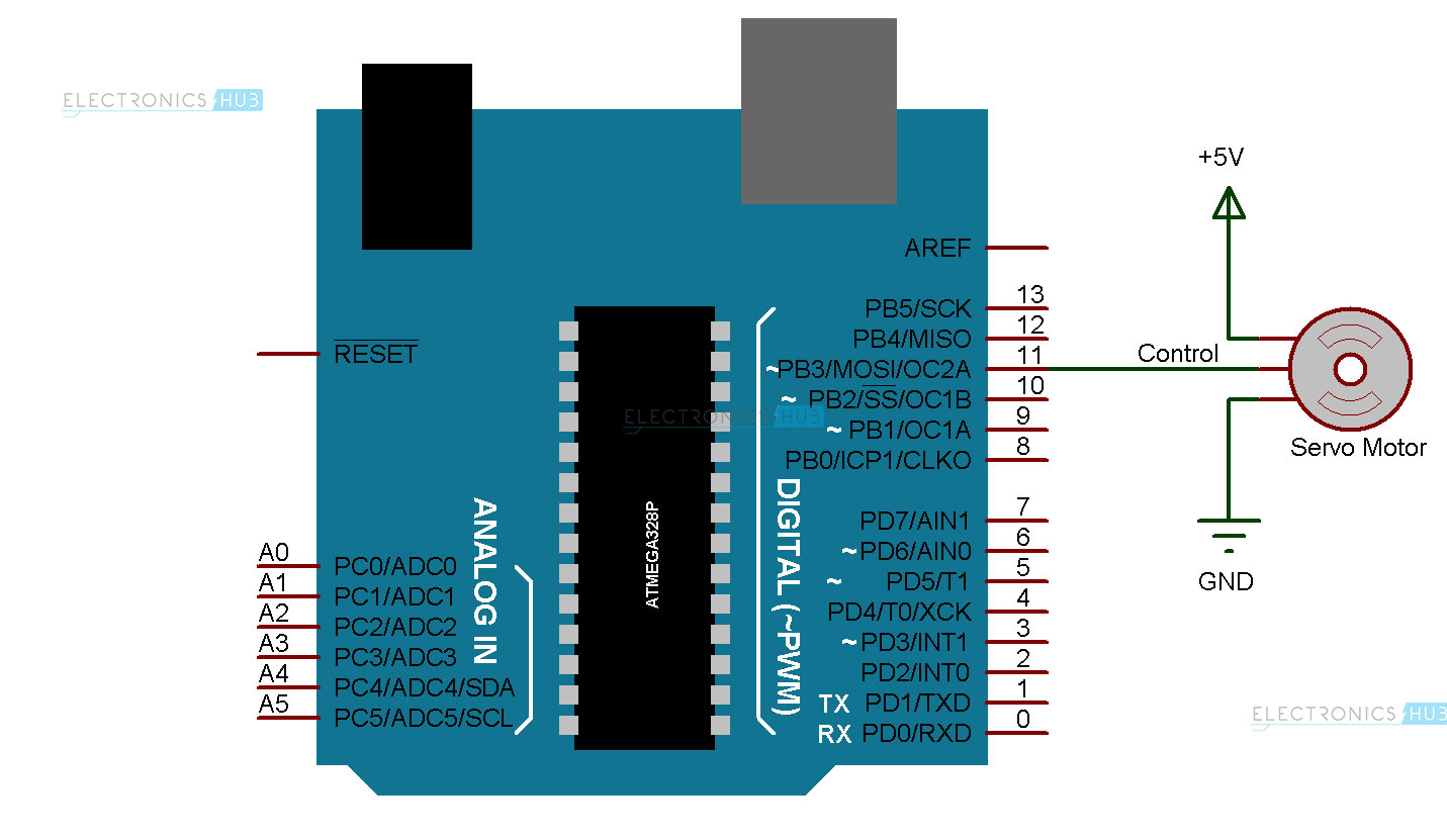
The program is uploaded to Arduino and when the system powered ON, the PWM control signal is given to the control wire of the servo motor. As a result, the servo motor rotates for 180 degrees in clock wise direction, one degree at a time. Once the servo motor reaches 180 degrees, it starts rotating in anti-clock wise direction to come back to the initial position. This process goes on until the system is powered OFF.
But for more precise control, we need to use the second mode and the following circuit must be used.

The potentiometer is connected to the analog input pin of the Arduino. The position of the potentiometer will determine the duty cycle of the PWM signal and this value, which will be in the range of 0 to 1023 (since Arduino UNO has a 10-bit ADC), is mapped to an angular position of 0 to 180 degrees. As a result, each degree of rotation of the servo motor can be precisely controlled by adjusting the position of the potentiometer.
Applications
- Servo Motors are one of the main components in precision control systems.
- Arduino based servo motors can be used small robotic applications, angular control of security cameras, etc.
- They can also be used in solar tracking system for increasing the efficiency of solar energy.

2 Responses
Nice project.
Thanks a lot¡ this page is awesome