Physical Mail or Post is a method of transporting documents, packages, cards, parcels and letters. This service is usually done by a postal service system. Mail is usually delivered by mail man post man to our homes. We get important documents like bills, invitations, bank statements etc. in mail.
If we don’t check our mail box regularly, we might miss the deadlines for payment of bills etc. It is a tedious job to regularly check for mail as mail boxes are often placed outside the house or in some cases, a common place at the end of the street.
Hence, in this project, a simple but efficient mail notifier system is designed using Arduino and few other components. This system notifies the user whenever there is a mail and hence avoiding the need to check for mail frequently.
The project is based on Arduino, RF Module (RF Transmitter and Receiver) and a light sensor (Photo resistor or LDR).
Circuit Diagram
Since the project is based on RF Modules, the circuit is divided in to transmitter and receiver.
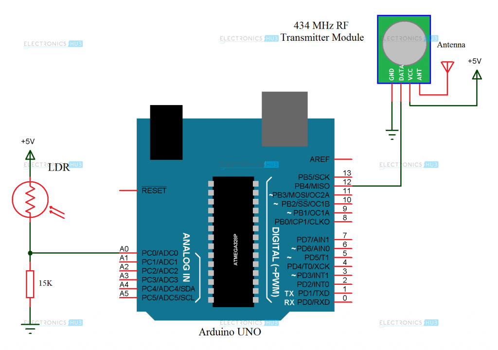
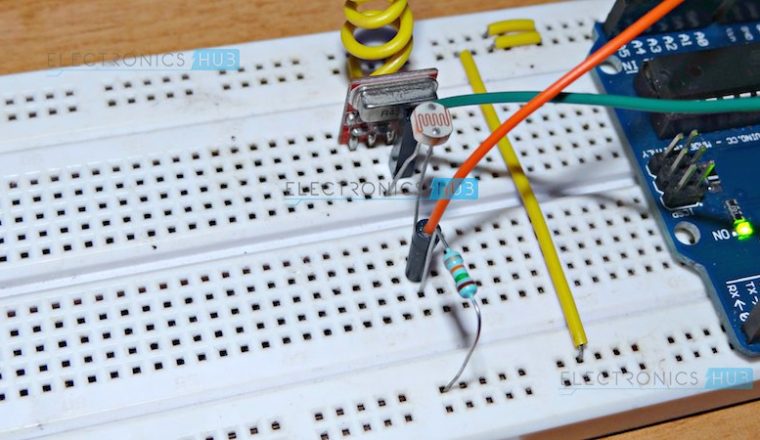
The following image shows the circuit diagram of the Transmitter or Sender part of the project.
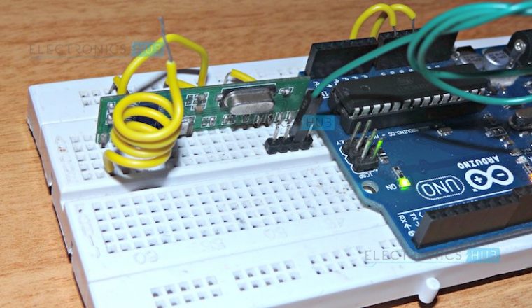
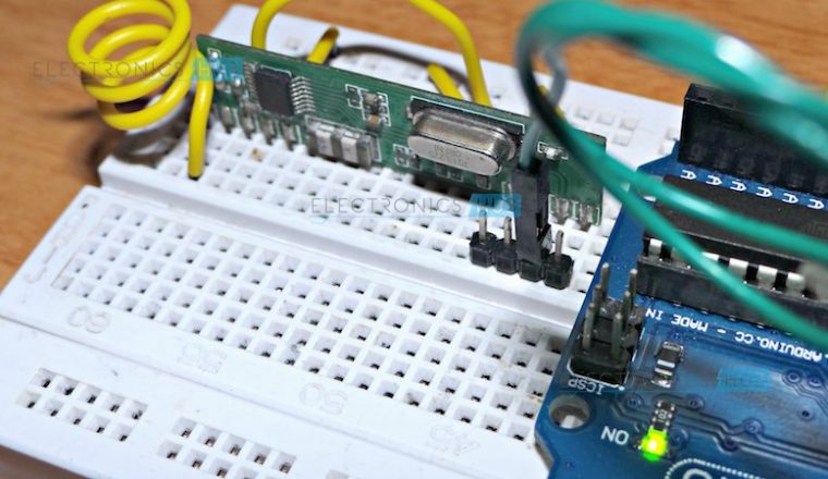
The following image shows the circuit diagram of the Receiver part of the project.

Components Required
Transmitter Part
- Arduino UNO (or any Arduino compatible board)
- 434 MHz (or 315 MHz) RF Transmitter Module
- Photo Resistor (Light Dependent Resistor – LDR)
- 15 KΩ Resistor (or 10 KΩ Resistor)
- Battery
- Bread board (Prototyping board)
- Connecting wires
Receiver Part
- Arduino UNO (or any other Arduino compatible board)
- 434 MHz (or 315 MHz) RF Receiver Module
- Power supply
- Bread board (Prototyping board)
- Connecting wires
Component Description
Arduino UNO:
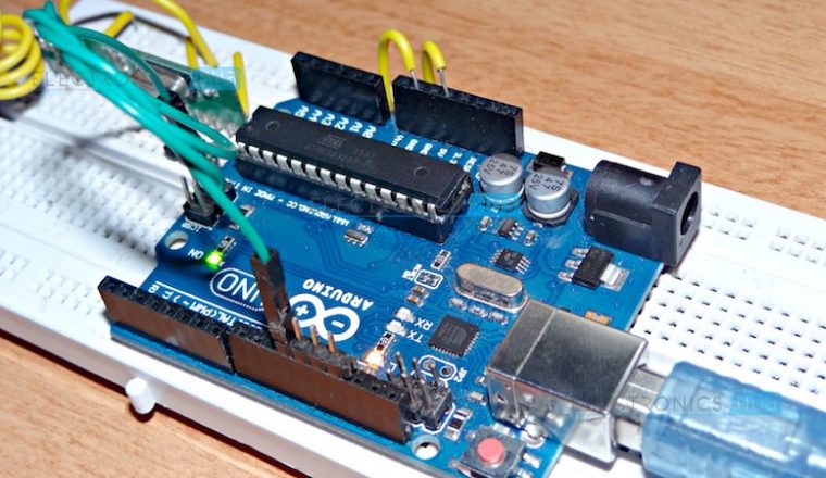
Arduino acts as the main controlling part of the project. We have used two Arduino boards in this project and to be more specific we have used Arduino UNO.
RF Transmitter and Receiver Module:
The 434 MHz RF Transmitter – Receiver pair is a cheap way to implement wireless communication. It can be used in wireless data transmission for different applications like RC cars, wireless doorbells, home automation etc.
Photo Resistor (LDR):
A Photo Resistor or Light Dependent Resistor (LDR) is an analog device, whose resistance varies according the ambient light incident on it.
Circuit Design
Transmitter Part
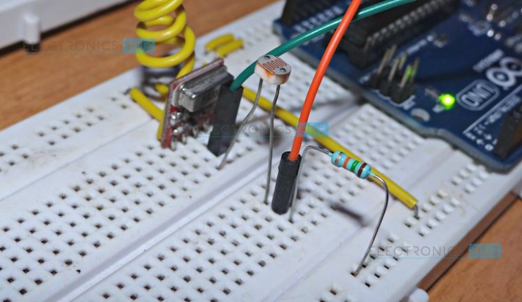
The transmitter part of the project consists of Arduino UNO, 434 MHz RF Transmitter Module and a photo resistor. The transmitter module used in the project consists of 4 pins. VCC is connected to 5V supply and GND is connected to ground terminal. These two terminals can be connected to the respective pins of the Arduino.
The data pin receives data from the Arduino UNO. So, it is connected to pin 12 of the Arduino UNO. Some RF Transmitter modules comes with antenna attached to the board.
For smaller distances, the antenna is really not necessary. But for larger distances i.e. over 10 meters, then we need to connect a 15 CM antenna (a simple wire will suffice).
Coming to the sensor part of the project, the LDR must be connected to the Analog IN pins of the Arduino. In order to convert the change of resistance to something which Arduino can easily understand, the LDR and an additional resistor (10 KΩ or 15 KΩ) are connected in a potential divider fashion (as LDR is basically a variable resistor) and the output of this potential divider is connected to the Analog Input A0 of the Arduino.
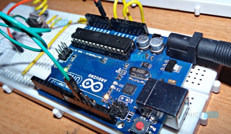
Receiver Part
The receiver part of the project consists of Arduino UNO board and the 434 MHz RF Receiver Module. As the aim of the project is to simply transmit the message on the event of reception of mail, no other components are used in the receiver section.
The receiver module has 4 pins on it. The VCC pin must be connected to 3.3V pin of the Arduino just to be safe (although the receiver module can tolerate 5V). The GND is connected to ground pin of the Arduino.
Arduino UNO receives data from the RF Receiver. Hence, the data out pin of the RF Receiver is connected to pin 11 of the Arduino. As mentioned in the transmitter part, a simple 15 CM long wire will act as the antenna.
Working Process
In this project, a simple mail alert system is developed using simple and cheap wireless communication devices. The aim of the project is to notify the user with a message whenever he/she receives a mail in their mailbox.
The main sensor used for detecting the mail is the photo resistor or LDR. Majority of mailboxes are open and shut type i.e. a small door must be opened and the mail must be placed inside the box.
If we place the LDR on the inside of that small door, it receives light only when the door is opened to insert a mail. As the LDR senses the changes in the ambient lighting (by changing its resistance accordingly), it can differentiate between a door – open scenario and a door – close scenario.
This change in the resistance is converted to a voltage with the help of the potential divider and is given to the Arduino’s analog input.
The Arduino then compares this value with a threshold value (must be tested for efficient detection) in the program. If the sensor value is less than the threshold, it means that the door is not opened and there is no mail yet. In this case, the Arduino send a message as “No mail” via the transmitter. The receiver receives this message and displays it on the serial monitor.
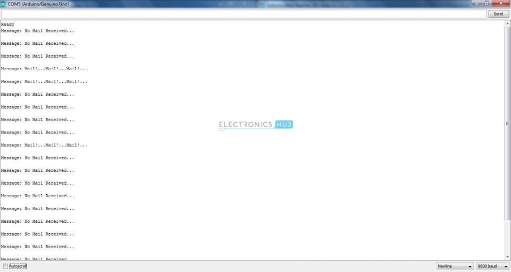
Similarly, if the sensor value is greater than the threshold value, it means that the door is opened and mail has been inserted. As a result, the Arduino transmits a mail arrived message which is again received by the receiver and displayed on the serial monitor.
Note: The project uses “VirtualWire.h” library for efficient working of the RF modules. It is an additional library and must be downloaded separately.
Applications
- As it is a simple mail notifier system, only messages are transmitted. For better notification, we can implement a buzzer system.
- The project can be further expanded by implementing a GSM Module which sends the user a message on his/her phone whenever a mail has been detected.


6 Responses
will you show the output of the mail notifier
Hey,
I do not quite understand how the Output will be shown? Is there an LED that flashes? Or does it constantly need to be connected to a PC ? Can you connect a small LCD Display to visualize an Inbox ?
Where should the Display be connected to ?
The way this is currently designed outputs messages to the serial monitor. The project could be modified to light an LED, sound a buzzer, send an email or SMS, display a message on an LCD…
How the two arduino’s will be connected?
With the 434MHz wireless transmitter and receiver.
How does it no when there’s mail if the the transmitter doesn’t have a arduino to power it?